Research paper
Development of Feeding Conveyor in Grain Stationery Thresher
Mohammed Ahmed Abd Elmowla1, Mohamed Hassan Dahab2 and Fatah El Rahman Ahmed EL Mahie3
1 Dept. of Agricultural Engineering, Faculty of Agriculture, Nile Valley University.
2 Dept. of Agricultural Engineering, Faculty of Agriculture, University of Khartoum.
3 Department of Mechanical Engineering, Faculty of Engineering and Technology, Nile Valley University.
Corresponding author: عنوان البريد الإلكتروني هذا محمي من روبوتات السبام. يجب عليك تفعيل الجافاسكربت لرؤيته.
A B S T R A C T
Development of Feeding Conveyor in Grain Stationery Thresher
تصميم وتطوير سير تغذية لدراسة المحاصيل الثابتة
محمد احمد عبد المولى ،1محمد حسن دهب 2و فتح الرحمن احمد الماحى3
1قسم الهندسة الزراعية، كلية الزراعة، جامعة وادي النيل
2قسم الهندسة الزراعية، كلية الزراعة، جامعة الخرطوم
3قسم الهندسة الميكانيكية، كلية الهندسة والتقنية، جامعة وادي النيل
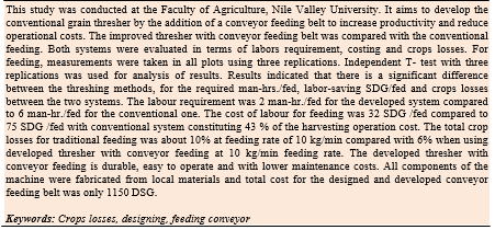
أجريت هذه الدراسة في كلية الزراعة- جامعة وادي النيل. تهدف هذه الدراسة لتطوير آلة درس الحبوب الثابتة بإضافة سير
تغذية لزيادة الانتاجية وتقليل تكاليف التشغيل. تم اجراء مقارنة بين اداء الدراسة باستخدام سير التغذية وبطريقة التغذية
التقليدية، من حيث احتياج العمالة، التكاليف والفاقد في المحصول. أظهرت النتائج تأثيرا عاليا ( )P >0.01لعملية التغذية بين
آلة دراسة الحبوب المطوره (بالسير الناقل) ودراسة الحبوب التقليدية (يدوية التغذية) في احتياج العمال وتكلفتهم وزمن العملية
وفاقد المحصول لعملية التغذية. ووجد اقل عدد للعمال ( 2عامل) فقط بالنسبة لآلة الدرس المطورة بينما ( 6عمال) في حالة آلة
درس الحبوب التقليدية، وكانت اقل تكلفة لعملية تغذية الفدان/عامل للدرس المطورة ( 32جنية سوداني) للفدان بينما تكلفة تغذية
آلة الدرس التقليدية ( 75جنية سوداني)، وكانت نسبة تكلفة العمال اقل بنحو .% 43وجملة فاقد الحصاد لعملية التغذية لآلة
الدرس التقليدية (يدوية التغذية) % 10بمعدل تغذية 10كجم/دقيقة مقارنة بـ % 6عند استخدام آلة الدرس المطورة (السير
الناقل) لنفس معدل التغذية. معظم مكونات التعديل في آلة درس الحبوب من المواد المحلية بتكلفة حوالي 1150جنية سوداني.
Mohammed A. Abd Elmowla et al. / Nile Journal for Agricultural Sciences Vol. 2, NO. 1 (2017) 74 - 88
Introduction
Different models of stationary grain threshers have been imported to Sudan (G.A.S., 1996). They are simple in design, easily maintained, consume little power (35 - 40 hp) and have been designed with simple threshing, cleaning and bagging units.
However, there are claims of injuries associated with the stationary thresher. Rawal (1988) reported that the human factors associated with thresher injuries were 73 %. These included inattentiveness, wearing of loose garments, overwork and physical incapability. Mufti et al. (1989) reported that belt entanglement, electric shock and feeding crop without safety were main reasons attributed to thresher injuries, they also added that the mechanical failures responsible for injuries were 17%. Kumar et al. (2000) stated that threshing machine recorded 2
% of total agricultural injuries though they are used only for a few days in the whole year. Morad (1997) investigated threshing machine performance and concluded that threshing losses as well as threshing cost can be minimized when the feed rate of 1 ton/h, drum speed of 25 m/s, and moisture content of 20 % are considered for the used machine.
The main objectives of this study was to design and to test the performance of feeding conveyor belt for grain stationary thresher, and to compare Labouring requirement and cost of the conventional and developed systems.
Materials and Methods Materials
The developed parts of the grain stationery thresher
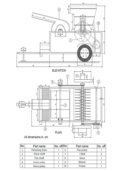
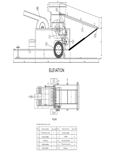
This study conducted at the faculty of agriculture, Nile Valley University in Darmali, North of Atbara. Thresher developed by El-mowla et al. (2014) was employed in the stationary thresher Elshams with its technical specification shown in Table (1). All experiments were conducted using a stationery thresher before and after development. The elevation and plan of stationery thresher machine before and after development are shown in Figs. (1) and (2), respectively. Experiments were conducted using two crops: wheat and faba beans.
Methods
The developed feeding conveyor
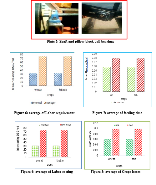
A feeding device in the developed threshing machine was designed and assembled to increase machine efficiency and to reduce traumatic injuries during threshing process. The developed feeding device in the thresher machine consists of four main parts as shown in plates (1) and (2).
Development of Feeding Conveyor in Grain Stationery Thresher
The frame
The frame consisted of inclined rectangular table of 245 × 197.5 cm. It was designed with these dimensions to help in handling the crops from the heap at an inclined surface of 35º to the feeding platform, which is at a height of 1.77 cm above the ground surface. This angle of elevation was determined through a micro-test by putting some faba bean and wheat crops on flat and smooth metal sheet, which was raised slowly from the horizontal position. The faba bean and wheat started to slide at an angle 37º. Therefore, a smaller angle 35º was chosen for calculation of the total length of the conveyor belt table by dividing the vertical height of the feeding platform 1.77 cm by sine 35º. Then an extra 39.88 cm were added to extend the length towards the threshing unit for a total length of 236 cm. The width of the thresher feeding plate frame was 120 cm. Therefore, the width of conveyor belt table was taken as 118 cm with 1 cm clearance at each side in order to have as great as possible conveyor belt area (Fig. 3).
Transmission system
The motion is transmitted from the threshing shaft connected to tractor P.T.O shaft, which provided with a fixed pulley of 20 cm diameter to transmit the motion through belt and pulleys to belt feeding shaft, which operate the belt for feeding the crop materials.
The belt drive and pulley
The distances between the centers of the driving shaft (threshing shaft 400 rpm) and the driven
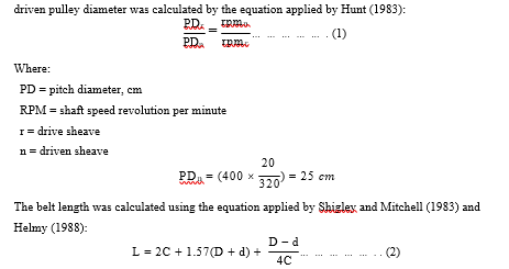
shaft (roller shaft 320 rpm) were 72.5 cm. The driven pulley was attached to the roller shaft. The driven pulley diameter was calculated by the equation applied by Hunt (1983):
Where:
L = effective length of the belt.
C = distance between centers of pulleys.
D = effective outside diameter of the large pulley (sheave). d = effective outside diameter of the small pulley (sheave).
12.5 − 10
L = 2 × 72.5 + 1.57(10 + 12.5) +4 × 72.5= 187.5 ??
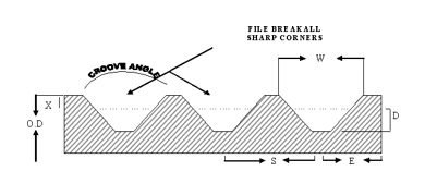
The nearest standard size of V-belts from Table (3); B187.5 V-belt was used for power transmission to the roller shaft when using the pulleys of 25 cm diameter.
The rollers, shafts and bearings
Two rollers 97.5 long and 10 cm diameter were installed to support the conveyor belt. The rollers were made of galvanized steel tubes welded to a steel shaft 2.5 cm diameter and 115 cm long. Each roller was supported by two pillow-block ball bearings. The front drive roller shaft was 115
× 9.7 cm, which was extended 8 cm to one side and 12.59 cm to the other side (the driven pulley side).
Selected conveyor belt dimensions
A flat belt with dimensions of 411.48 cm length, 80.01 cm width and 0.203 cm thickness was tatted between drive and driven shaft (equation 2):
Fenders
Two side fenders, made from sheet metal (197.5 × 20 cm), were attached to each side of the conveyor table to prevent the conveyed crop from falling to the sides (Fig. 4).
Supporting pipe
Supporting pipe consisted of two telescoping pipes. The inner pipe diameter was 3.4 cm and length 67.5 cm while the outer pipe diameter was 4.1 cm and length about 117 cm. The pipes were connected to the conveyor belt table through pin joints.
Operational performance
The man-hours per fed was determined using the following formula:
Man-hours/fed = (L × t) / A……... (4)
Where:
L = number of labours.
t = spent time (hours).
A = the area of collected crop (fed).
Time required during the feeding threshing operation was recorded using a stopwatch.
Crop losses
The total crop losses percentage (TCL) was calculated before and after developing the thresher using the following equation (Mishram and Desta 1990):
Tcl % = (Tfe / Tcr) x 100……..(5)
Where:
Tcl= total crop weight losses percentage (kg) Tcr= total crop weight before feeding (kg)
Tfe = total crop weight after feeding (kg)
Machine developing cost
Cost of the developed system divided into:
- Cost of linking the developed feeding device to thresher (iron angles, iron flanges, iron sheet, other tools).
- Cost of power transmission parts (Table 4).
Results and discussion
Labour requirement and costing evaluation
The labour requirement was only 2 man-hr/fed for the developed thresher as compared to 6 man- hr/fed with the undeveloped machine, which was a labour saving of 43 %. The cost of harvest was 32 DSG/fed as compared to 75 SDG/fed with undeveloped machine (Figs. 5 and 6). However, statistical analysis showed significant differences between the two threshing operation methods in terms of labour requirement and harvesting cost.
Time of feeding
The obtained results indicated highly significant difference (P< 0.01) between the two threshing operation methods. As shown in Figure (6), conventional threshing operation resulted in higher man hrs/fed (0.08 hr) compared to the developed thresher (0.03 hr). However, the improved developed thresher with conveyor feeding resulted in highly significant savings of 2 man-hrs/fed compared to the undeveloped thresher with direct manual feeding. Therefore, the use of conveyor feeding belt reduced the required threshing time. El-Awad (2007) found that, such designed conveyor-feeding belt could be used in the thresher feeding of grains, so as to improve the threshing operation performance.
Crops losses measurement
Figure (7) illustrated that at a feeding rate of 10 kg/min, the maximum values of total crop losses percentage (10 %) was obtained when using direct manual feeding threshing, compared to the developed conveyor feeding threshing machine with 6 % crop losses. On the other hand, increasing feeding rate from 2.5 to 10 kg/min increased the total crops losses by 20 % and 30 % for the developed and undeveloped threshing machine, respectively.
Statistically the difference between the two threshers was highly significant. Results indicated that the developed machine decreased the percentage of grains losses compared to the undeveloped machine due to the uniform distribution of wheat plants along the developed feeding conveyor, which enable plants to enter the threshing chamber from the wheat spikes direction, thus uniform impact is resulting in low percentage of grains losses. Results also showed that, the unstrapped legumes loss increased by increasing feeding may be attributed to the increase in the thickness (bulking) of crops. However, these results are in agreement with Badawi (2002).
Conclusion
A feed conveyor thresher was successfully developed and evaluated for its performance. The overall performance of the developed feeding, conveyor thresher was satisfactory for threshing of faba bean and wheat crops. The development of mechanical threshers has clearly proved to be necessary in order to reduce the drudgery of threshing works to a great extent.
References:
Badawy, M.E. (2002). Modification and evaluation of paddy rice thresher to suit flax deseeding.
Misr J. Ag. Eng., 19(4): 881– 900
El-Awad, Sh. A, A.E.S. and M.A.A. (2007). Improvement of the modified grain thresher for groundnut threshing. AMA, 38(3): 67-72
El-mowla, M.A.; Dahab, M.H. and Elmahie, F.A. (2014). Improvement and performance evaluation of stationary combine thresher. International Journal of Engineering and Scientific Research, Volume 2, Pp:41-51
G.A.S. (1996). General Administration of Statistics Annual report, Ministry of Agriculture and Forestry, Khartoum, Sudan.
Development of Feeding Conveyor in Grain Stationery Thresher
Helmy, M.A. (1988). Threshing parameters affecting the performance of local and foreign wheat threshing machines. Misr. J. Ag. Eng., 5 (4): 329-343.
Hunt, D. (1983): Farm power and machinery management. 8th ed. Iowa State University Press, Ames, Iowa, USA, 364-368.
Kumar, A; Varghese, M. and Mohan, D. (2000). Equipment related injuries in agriculture: an international perspective. J. Injury Preview. Control, 7(3): 175-186.
Mishram, T.N. and Desta, K. (1990). Development and performance evaluation of a sorghum thresher. Agric. Mech. In ISIA, 21 (3): 33-37.
Morad, M.M. (1997): Cost analysis and energy requirements for threshing wheat. Misr. J. Ag.
Eng. 14 (1): 93-105.
Mufti, I.; Ahmad, S.I. and Majid, A. (1989). Farm accidents in Pakistan. Agric. Mech. Asia Africa Latin America 20, 73-75.
Rawal, H.S. (1988). Proper selection and safe use of power wheat thresher. Prog. Farming. 24 (7): 12-14.
Shigley J.E. and Mitchell, L.D. (1983). Mechanical Engineering Design. Fourth edition. Mc Graw-Hill Book Company.
Mohammed A. Abd Elmowla et al. / Nile Journal for Agricultural Sciences Vol. 2, NO. 1 (2017) 74 - 88
Table 1: Technical specification of stationery thresher “ElSHAMS”
|
Technology specification |
ElSHAMS |
|
Length (mm) |
4020 |
|
Width (mm) |
2200 |
|
Height (mm) |
24000 |
Table 2: Standard V-belts sections
|
Belt section |
Width a (in) |
Thickness b (in) |
Hp range one or more belts |
Minimum sheave diameter (in) |
|
A B C D E |
½ 21/32 7/8 11/4 11/12 |
11/32 7/16 17/32 ¾ 1 |
¼ - 10 1 –25 15 –100 50 –250 100 and up |
3.0 5.4 9.0 13.0 21.6 |
Source: Shigley and Mitchell, 1983
Table 3: Groove dimensions and tolerances for multiple V- belt Sheaves
|
Belt |
Pitch diameter |
Groove angle |
Standard groove Dimension (inch) |
Deep groove Dimension (inch) |
|||||||||
|
Minimum recommend ed |
Range |
W |
D |
X |
S’ |
E |
W |
D |
X |
S’ |
E |
||
|
B |
3.0 |
2.6 to 5.4 Over 5.4 |
±1/2˚ |
(2) |
±.031 |
… |
±.031 |
(3) |
(2) |
±.031 |
… |
±.031 |
(3) |
|
34˚ 38˚ |
.494 .504 |
.490 |
.125 |
5/8 |
3/8 |
.589 .611 |
.645 |
.28 |
3/4 |
7/16 |
|||
Source: Machinery's Handbook (2000)
Development of Feeding Conveyor in Grain Stationery Thresher
Table 4: Cost of developed parts
|
Items |
Price in SDG |
|
Fasteners, shim, angles etc. |
250 |
|
Workshop and labour |
500 |
|
Supporting pipe |
100 |
|
Pulleys and rollers |
0200 |
|
Conveyer belt and V-belt |
0100 |
|
Total |
1150 |
Mohammed A. Abd Elmowla et al. / Nile Journal for Agricultural Sciences Vol. 2, NO. 1 (2017) 74 - 88
Figure 1: Elevation and plan of stationery thresher before development
Figure 2: Elevation and plan of stationery thresher after development
Mohammed A. Abd Elmowla et al. / Nile Journal for Agricultural Sciences Vol. 2, NO. 1 (2017) 74 - 88
Mohammed A. Abd Elmowla

